SQUIRES VIEW ENERGY CENTRE, STOKE-ON-TRENT
SSE
BACKGROUND
The Squires View Energy Centre will ultimately become the back-up energy centre for the Stoke-on-Trent Heat Network (STHN) scheme and is being developed by SSE with support from Stoke-on-Trent City Council as part of the overall district heating network programme.
The STHN scheme (also being developed by SSE) will utilise heat extracted from a yet to be built Energy Recovery Facility (ERF) in Hanford to the south of the Squires View Energy Centre. The ERF is expected to be operational in 2031 and will connect into the district heat network at the same time.
As a result, in the intervening period, the Squires View Energy Centre will be the sole supplier of heat for the 21km distribution network, feeding a variety of buildings throughout the city, including educational, local authority and NHS connections.
OUR ROLE
Following completion of the RIBA Stage 3 design for the STHN, D3A was appointed by SSE to provide the design, up to RIBA Stage 3, for the Squires View Energy Centre, including assistance with the planning application process. As Lead Designer and Architect, D3A also coordinated the variety of wider design disciplines required to deliver the RIBA Stage 3 output (including MEP, Civil and Structural Engineering and Fire Engineering) and delivered a spatially coordinated design that fully met the original design brief.
The team also collaborated closely with the client appointed Planning Consultant on a wide range of planning reports and planning related tasks including completing the planning drawing pack and Design and Access Statement, ensuring an integrated approach.
Critical to the role that D3A undertook was its District Heating Network design capability and track record of delivering the buried network design for Stoke. This enabled the Energy Centre design to be developed with the overall operational philosophy in mind.
OUTCOME
Whilst the Squires View Energy Centre was designed to house the heating network’s primary generation plant; including the main heat source, thermal storage, and supporting infrastructure, there were a number of other challenges to consider throughout the programme.
One of the biggest of these challenges was the site footprint. The location of the Energy Centre had to be carefully considered due to the limitations and location of the site which also included a wide strip of trees, facing the main road.
Throughout the design process a series of layouts were developed to maximise the use of the available space, along with swept path analysis to accommodate large vehicular access, parking and provisioning for the location of both the Thermal Store and fuel storage.
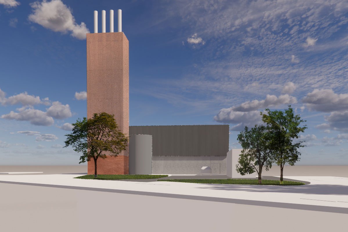
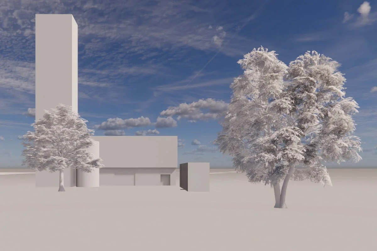
The developed design at RIBA Stage 3 is, in essence, a large-scale cube with a monolithic form and the chimney flue stack positioned towards the front, giving it deliberate prominence. The internal layout of the building has been influenced by the need to separate the industrial plant room areas and spaces for manned activities (welfare, office, meeting room etc.).
In addition to assessing space efficiency, we also looked at the materiality of the scheme to ensure its suitability for the proposed context, as well as allowing for maximum effectiveness of construction.
D3A designed a tripartite solution to the external material strategy using a palette of industrial materials, consisting of the flue chimney element and upper-level cladding sitting above the lower-level plinth.
In summary, the original project brief presented by SSE was challenging from both technical and programme related aspects. However, with D3A’s robust approach to project management, supported by a highly skilled multi-disciplinary team, alongside a close working relationship with the client and planning consultant, the programme was delivered on time, with both SSE and Stoke-on-Trent Council highly satisfied with the output.
It’s also worth noting that as part of the scope, D3A also took on the role of QS at both RIBA Stages 2 and 3, providing cost plans that would enable the data to be used in the client’s commercial modelling and as a basis for future tendering of the project.


